Examining the landscape
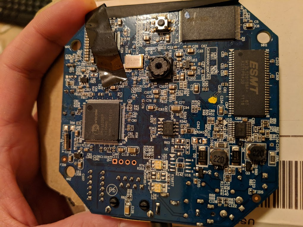
In part two I covered how I was able to make use of the cameras by first attempting to crack a known root password hash (which wound up not working for this firmware) and then later re-flashing the camera with alternative firmware. Even though I accomplished my primary goal of making the Verizon-branded camera usable I still felt I could take this further by actually cracking the default admin credentials and avoiding the need to re-flash these cameras. I started by taking a closer look at the camera and its components. I had already identified and utilized the UART points, but hadn’t yet looked very closely at other items. One of the easiest things you can do is take FCC ID and look it up in the FCC database. I did this and although it didn’t provide me with anything especially helpful it was an interesting read. After this I decided to single out each component and research them. The picture below shows the front side of the main board. I’m particularly interested in the two chips in the top right corner of the board, but we’ll get there.
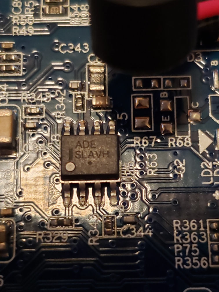
I started with the small 8-pin chip in the middle of the board. I had originally hoped this was a standard EEPROM chip as they are fairly easy to read, but taking a closer look it didn’t seem to be the case. The text read “ADE SLAVH“. I was unable to find anything on this, so it was clearly not an EEPROM.
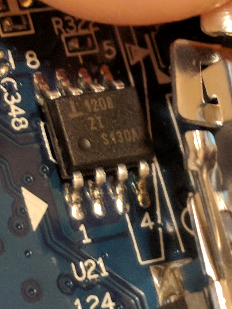
I then moved to another 8-pin chip on the back of the board (next to the wireless interface module). After doing a little research on this chip it seemed to be a Renesas ISL 1208 RTC (real-time clock).
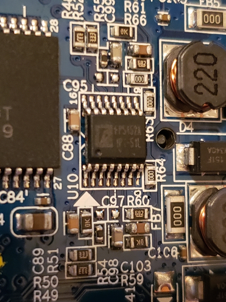
The next chip was one to the right on the front side of the board. It was a 16-pin chip, but I had trouble finding anything about this one. It was clear this wasn’t one that would be useful at this point, so I moved on.
The next chip I focused on was one of the two larger ones in the upper right of the front side of the board. This chip was labeled ESMT M12L128168A. It also had a matching partner on the direct opposite side of the board. When looking this up it wound up being a 16MB RAM chip. These two 16MB chips align with the 32MB of RAM in the boot output I observed via UART back in part one.

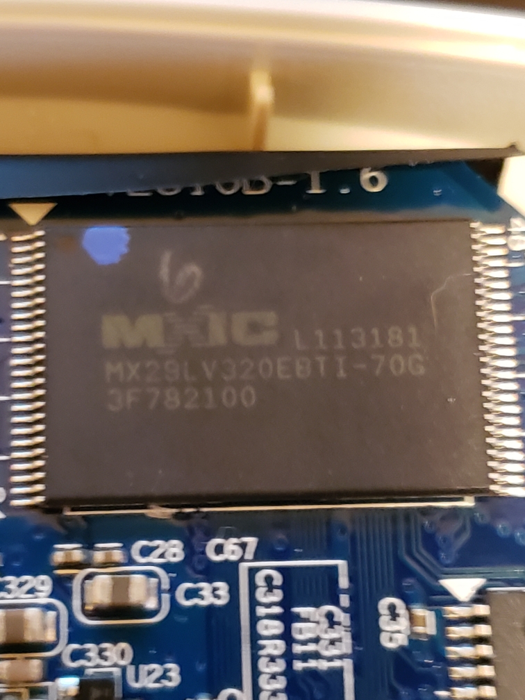
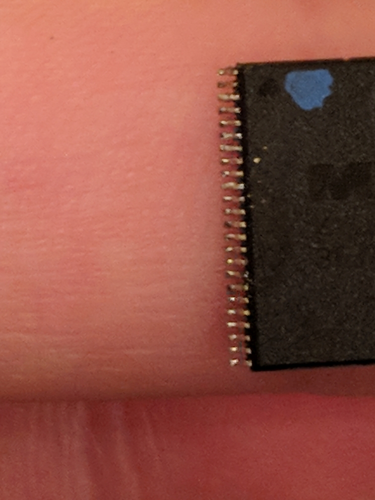
The last chip I moved to was one reading MX29LV320EBTI-70G. This one was sitting right next to the RAM chip above. A quick search revealed that this is actually a Macronix 4MB 48-PIN NOR parallel flash chip. This also aligned with the boot output from part one. During bootup the bootloader referenced a 4MB flash. This was the component to focus on.
Extracting a surface-mount device component
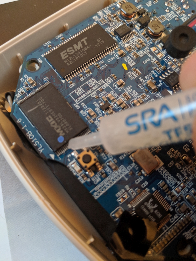
Now that I knew which chip was the flash chip it was time to attempt extracting it. I had never attempted the extraction of such a small component before, so I did some research into methods. I found that there are special low melting point alloys that are meant for just this type of task. I chose to go with SRA Fast Chip KIt SMD Removal Alloy. It was relatively cheap and available on eBay. Another popular choice for this task is Chip Quik which looks to be identical, but slightly more expensive.

To use these products you take the included flux (or a regular rosin flux) and cover all pins on the chip. You then melt a small amount of the alloy and cover all pins with it. Once everything is covered you try to keep the alloy melted by running the iron over the alloy with it while carefully extracting the chip with tweezers.
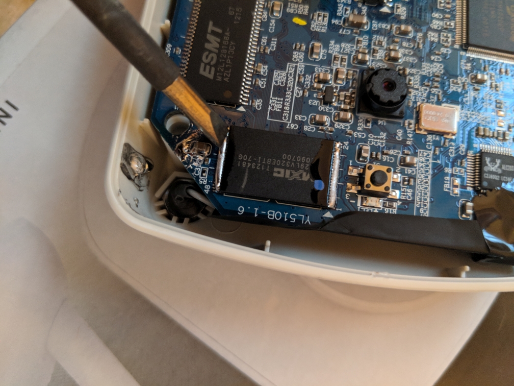
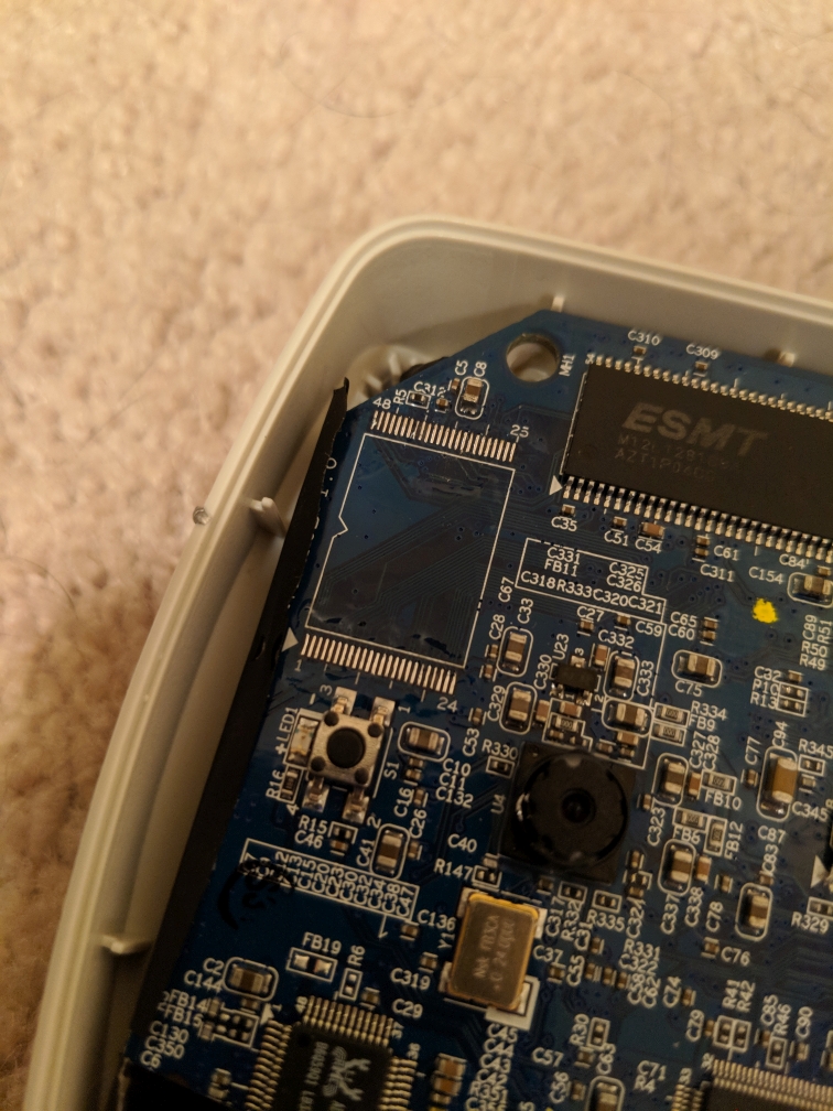
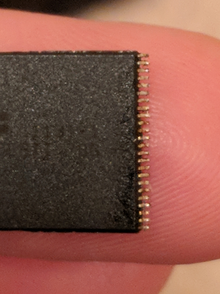
Once the chip has been pulled you can clean up the board with the iron (if you are planning to re-solder a chip there). The chip was a little more tedious to clean up. I carefully ran the iron’s flat tip over the pins while slowly dragging the chip across cardboard. The alloy came off in small streaks with each pass. The chip needs to be free of any bridging in order to be read properly.
Reading a NOR parallel flash chip
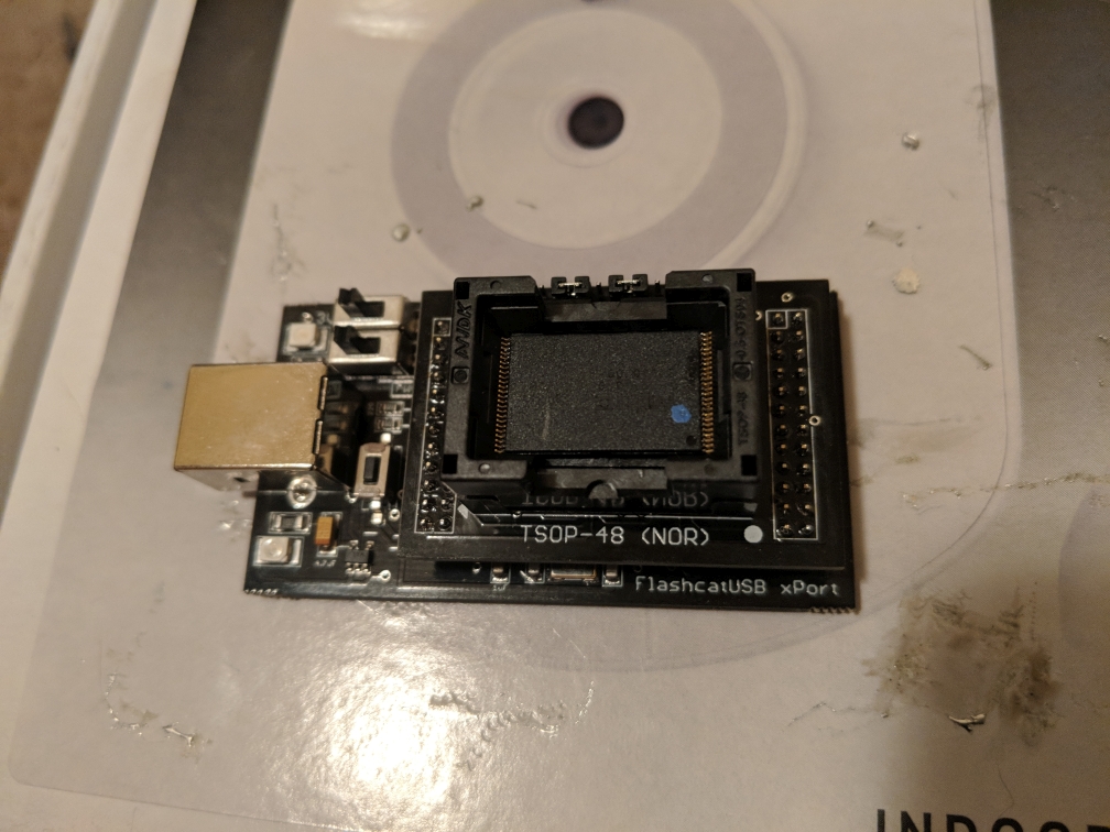
Reading a parallel flash chip can be a bit difficult. There are a lot of pins to communicate with and it all has be done in a specific order. Communicating with something like a standard 8-pin EEPROM is much easier. I was able to find someone using an Arduino to read a TSOP-48 NOR flash chip like this one, but I decided to take an easier route as I had already put a good amount of time into this project. I looked into different flash readers/writers and came across the FlashcatUSB xPort with the TSOP-48 adapter. It was relatively cheap and supported this chip along with many many others. I’m sure I’ll be able to make use of it in the future. Setup was easy and I was able to successfully pull an image from the chip.
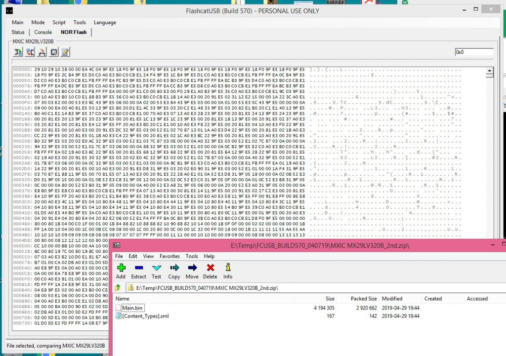
Now that I had a binary image of the chip I could start digging for what I was after… the default username/password for the admin console. In part one we learned the partition layout from the bootup output:
 Creating 9 MTD partitions on "plnormtd":
 0x00000000-0x00008000 : "bootloader"
 0x0000c000-0x0000e000 : "MAC"
 0x000e0000-0x00400000 : "SQUASHFS"
 0x0000e000-0x00010000 : "LOGO Image"
 0x00020000-0x00400000 : "Kernel+FS"
 0x00000000-0x00400000 : "ALL"
 0x0000a000-0x0000c000 : "HTTPS CA"
 0x00010000-0x00020000 : "CONFIG"
 0x00008000-0x0000a000 : "Reserve"
The “CONFIG” partition is usually what holds the persistent device configuration in plain-text on these types of devices. I loaded the image into hexedit and started working my way down from 0x00010000… and there it was! Some developer at Verizon has a sense of humor. I finally had what I really wanted from the beginning… the default admin console username/password. I tested it immediately and it worked. I also verified that once in the console I could change the username/password along with any other settings and they persisted a reboot. The admin console was almost identical to the default Sercomm web console. All the same configuration options were present.
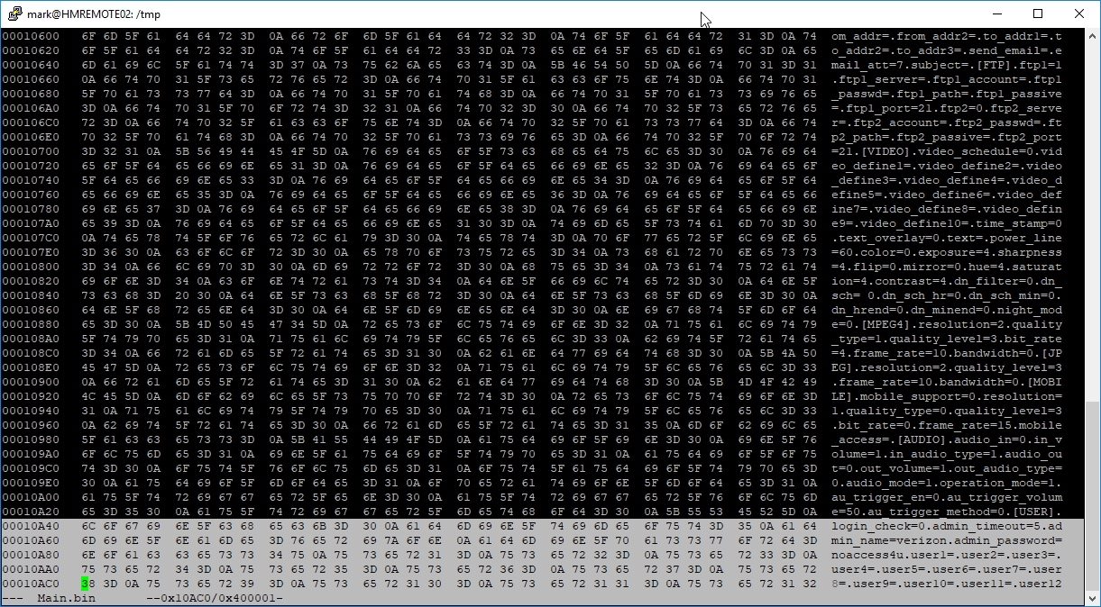
admin_name=verizon
admin_password=noaccess4u
I also extracted the Squashfs filesystem for examination. I verified that the root password was definitely not the manufacturer default that I had cracked in part two. It is actually generated during the boot process. I may possibly go into breaking this down in a part four post, but for now I accomplished exactly what I set out to do. I obtained the default admin credentials for a camera that Verizon was trying to keep you locked out of. The cameras are now fully functional as-is no flash required.